Central Solenoid
The central solenoid (CS) is a PF coil used during start-up and during the burn phase to create and
maintain the plasma current by electromagnetic induction. Swinging (changing) the current through
the central solenoid causes a change in the flux linked to the plasma region, inducing a current in
it. PROCESS calculates the amount of flux required to produce the plasma current, and also the
amount actually available. The code measures the magnetic flux in units of Volt.seconds (= Webers).
Switch iohcl controls whether a central solenoid is present. A value of 1 denotes that this coil
is present, and should be assigned a non-zero thickness dr_cs. A value of iohcl = 0 denotes
that no central solenoid is present, in which case the thickness dr_cs should be zero. No PF
coils should be located at positions defined by i_pf_location(j) = 1 if no central solenoid is present.
The central solenoid can be either resistive or superconducting (controlled via switch i_pf_conductor as
for the other PF coils), and if superconducting, switch i_pf_superconductor determines the superconducting
material to use - its value is used like isumattf and i_pf_superconductor. The copper fraction (by volume)
of the superconducting strands is fcuohsu.
CS Class | CSCoil
CS Geoemetry | calculate_cs_geometry()
This method calculates the CS geometry parameters. The CS is assumed to be a perfect cylinder of uniform thickness.
-
The mean radius of the middle of the CS is given by:
\overbrace{r_{\text{CS,middle}}}^{\texttt{r_cs_middle}} = dr_{\text{bore}} + \frac{dr_{\text{CS}}}{2} -
The half height of the CS is set relative to that of the inside height of the TF and can be scaled by changing the input value of
f_z_cs_tf_internal:\overbrace{z_{\text{CS,half}}}^{\texttt{z_cs_half}} = \overbrace{z_{\text{TF,inside-half}}}^{\texttt{z_tf_inside_half}} \times \texttt{f_z_cs_tf_internal} -
The full height of the CS is thus simply given by
\overbrace{dz_{\text{CS}}}^{\texttt{dz_cs_full}} = z_{\text{CS,half}} \times 2Along with the upper and lower dimensions:
z_{\text{CS,upper}} = z_{\text{CS,half}}z_{\text{CS,lower}} = -z_{\text{CS,upper}} -
The outboard edge of the CS is given by:
r_{\text{CS,outer}} = r_{\text{CS,middle}} + \frac{dr_{\text{CS}}}{2} -
The inboard edge of the CS is given by:
r_{\text{CS,inner}} = r_{\text{CS,outer}} - dr_{\text{CS}} -
The full radial width of the CS is given by:
dr_{\text{CS,full}} = 2 \times r_{\text{CS,outer}} -
The full poloidal cross-sectional area is given by:
\overbrace{A_{\text{CS,poloidal}}}^{\texttt{a_cs_poloidal}} = dr_{\text{CS}} \times dz_{\text{CS}} -
The full top-down toroidal cross-sectional area is given by:
\overbrace{A_{\text{CS,toroidal}}}^{\texttt{a_cs_toroidal}} = \pi \left(r_{\text{CS,outer}}^2 - r_{\text{CS,inner}}^2 \right)
EU-DEMO Turn Geometry | calculate_cs_turn_geometry_eu_demo()
This superconducting turn structure for the CS assumes a rectangular turn shape with a "stadium"-shaped cable area3.

The turn geometry is calculated as follows:
-
The vertical height of the turn is given by:
dz_{\text{CS,turn}} = \sqrt{\frac{A_{\text{CS,turn}}}{\texttt{f_dr_dz_cs_turn}}}\texttt{f_dr_dz_cs_turn} is the intended length to height ratio of the turn
-
The radial width or length of the turn is now given by:
dr_{\text{CS,turn}} = \texttt{f_dr_dz_cs_turn} \times dz_{\text{CS,turn}} -
The radius of the corners of the cable space is given by:
r_{\text{CS,cable space corner}} = - \frac{dr_{\text{CS,turn}}-dz_{\text{CS,turn}}}{\pi} + \sqrt{\left(\frac{dr_{\text{CS,turn}}-dz_{\text{CS,turn}}}{\pi}\right)^2+ \frac{dr_{\text{CS,turn}}dz_{\text{CS,turn}}(4-\pi)r_{\text{CS,turn corners}}^2 - (A_{\text{CS,turn}}\times \texttt{f_a_cs_turn_steel})}{\pi}} -
The thickness of the conduit around the cable space is given by:
dz_{\text{CS,turn conduit}} = \frac{dz_{\text{CS,turn}}}{2} - r_{\text{CS,cable space corner}}In this model the vertical and radial conduit thicknesses are equal so:
dr_{\text{CS,turn conduit}} = dz_{\text{CS,turn conduit}}
CS Current Filaments | place_cs_filaments()
General calculations | ohcalc()
Self peak bore magnetic field | calculate_cs_bore_magnetic_field()
The self induced peak field at the central bore of a homogenous current density rectangular cross-section solenoid is given by:
where \alpha = \frac{r_{\text{CS,outer}}}{r_{\text{CS,inner}}}, is the ratio of the outer and inner radii of the solenoid and \beta = \frac{z_{\text{CS,half}}}{r_{\text{CS,inner}}}, is the ratio of the solenoid half height to its inboard radius.
This is Equation 3.13 from "Case Studies in Superconducting Magnets"2.
Self peak on coil magnetic field | calculate_cs_self_peak_magnetic_field()
The peak field at the bore of the central solenoid will not be the same as that felt by the
conductors inside the structures. So we cannot use the bore value directly calculated by
calculate_cs_bore_magnetic_field().
We need to know the peak field on the conductor if we are to design a superconducting
central solenoid that has enough margin. Fits to data1 for different ranges of \beta
have been calculated as follows to scale the bore field value by:
-
\beta > 3.0
B_{\text{conductor,peak}} = B_0 \times \left(\frac{3}{\beta}\right)^2 \times (1.007 + (\alpha -1.0)\times 0.005) \\ +\left(1.0- \left(\frac{3}{\beta}\right)^2\right) \times (J_{\text{CS}}dr_{\text{CS}}) -
2.0 < \beta \le 3.0
B_{\text{conductor,peak}} = B_0 \times \left(1.025-(\beta-2.0)\times 0.018\right) + (\alpha -1.0) \\ \times (0.01-(\beta-2.0)\times 0.0045) -
1.0 < \beta \le 2.0
B_{\text{conductor,peak}} = B_0 \times \left(1.117-(\beta-1.0)\times 0.092\right) + (\alpha -1.0) \\ \times ((\beta-1.0)\times 0.01) -
0.75 < \beta \le 1.0
B_{\text{conductor,peak}} = B_0 \times \left(1.3-0.732(\beta-0.75)\right) + (\alpha -1.0) \\ \times 0.2((\beta-0.75)-0.05) -
\beta \le 0.75
B_{\text{conductor,peak}} = B_0 \times \left(1.65-1.4(\beta-0.5)\right) + (\alpha -1.0) \\ \times 0.6((\beta-0.5)-0.2)
Axial Stress | calculate_cs_self_axial_stress()
The vertical (axial) force at location z for a "thin-walled" solenoid (\alpha = 1) with a uniform surface current density and its midplane at z=0 is given by Equation 3.40 in "Case studies in superconducting magnets" 2:
The ellipticic integral moduli, k_{b-}^2, k_{b+}^2, k_{2b}^2
and k_b is given by:
Here K(k) and E(k) are the complete elliptic integrals, respectively of the first and second kinds.
Non thin-walled solenoids
For solenoids that can be classed as "thick-walled" (\alpha > 1), the coil has to be divided radially into several thin-walled solenoids. This is not currently performed though more info can be found in Section 3.5.5 of "Case studies in superconducting magnets" 2.
The axial compressive force at z in an isolated solenoid increases from 0 at z = dz_{\text{half}} to the maximum at the midplane, F_{z}(0).
The axial stress in the steel is given by:
where F_z is the axial force, f_z is the fraction of the horizontal cross-section occupied by steel, and A_z is the area of the horizontal cross-section.
The fraction of the horizontal cross-section occupied by steel is calculated assuming that the conductor is square and has a steel jacket with the same thickness on all four sides, giving:
Peak Axial Stress | calculate_cs_self_peak_midplane_axial_stress()
By inserting z=0 into the general axial stress equation above we can get an expression for the midplane force which is the peak value. This is also given as Equation 3.41 in "Case studies in superconducting magnets" 2:
where the modulus k_{2b} is given by
and k_b is given by:
Radial stress | calculate_cs_radial_stress()
The self induced radial stress is calculated using Equation 4.11 from "Superconducting magnets" 1.
Where:
- \epsilon = \frac{r}{r_{\text{CS,inner}}}
- \alpha = \frac{r_{\text{CS,outer}}}{r_{\text{CS,inner}}}
The terms K and M are given by:
Hoop stress | calculate_cs_hoop_stress()
The hoop stress is calculated using Equation 4.10 from "Superconducting magnets" 1. This is divided by the fraction of the area occupied by steel to obtain the hoop stress in the steel, \sigma_{\theta}.
Where:
- \epsilon = \frac{r}{r_{\text{CS,inner}}}
- \alpha = \frac{r_{\text{CS,outer}}}{r_{\text{CS,inner}}}
The terms K and M are given by:
Assumption of outer field, B_{\text{CS,outer}}
In this case we currently assume that B_{\text{CS,outer}} = 0. This is the same as that for an infinite solenoid. Approximation of the outboard field is currently not performed.
Fatigue
If the the reactor is assumed to be pulsed, the CS must be assessed against fatigue.
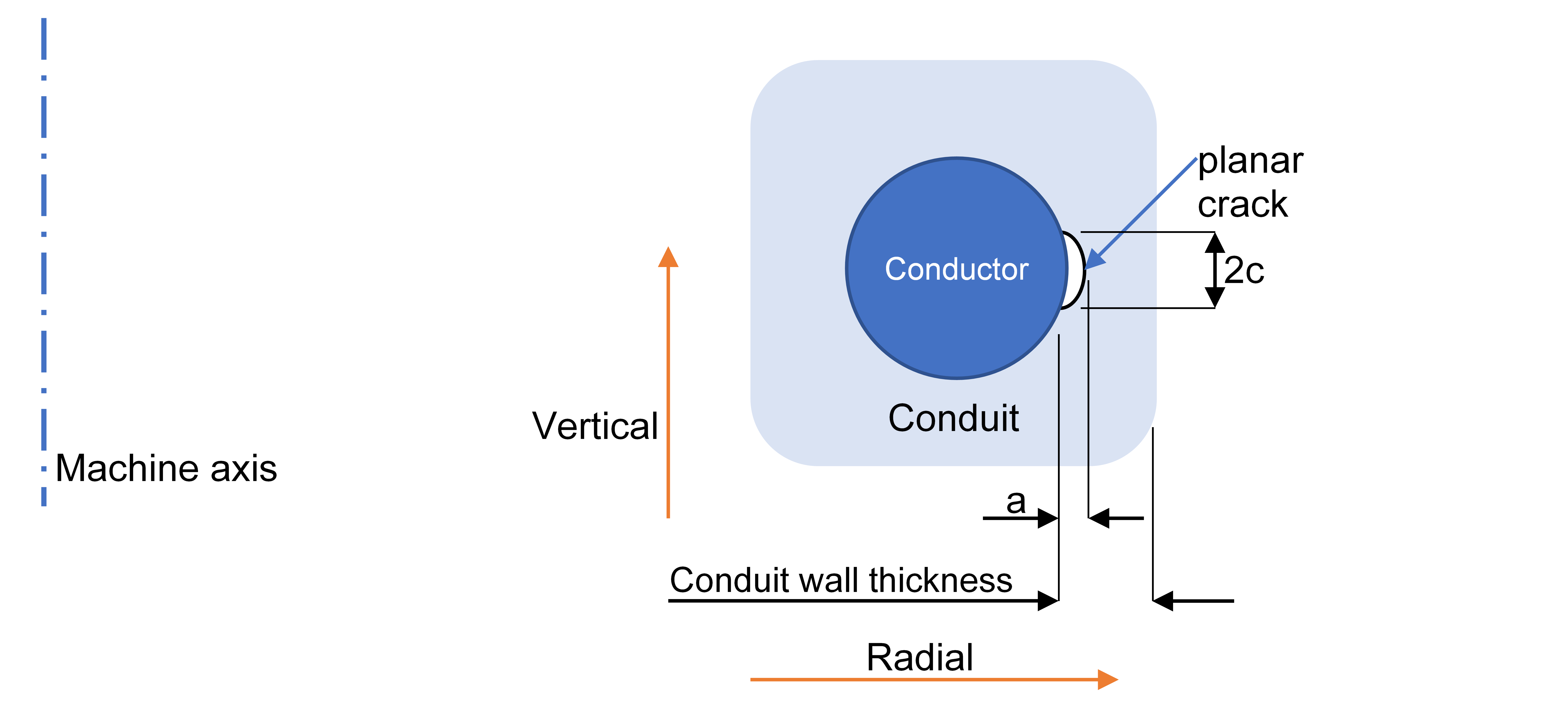
A simple crack growth model based on Linear Elastic Fracture Mechanics is used to estimate the allowable hoop stress in the conduits. The model follows the method described in the ITER Magnet Structural Design Criteria, using the Paris law to model the growth of a planar elliptical crack across the thickness of a plate with the width and thickness of the conduit wall. The Paris law states that the crack growth rate follows a power law:
where a is the size of the crack, N is the number of cycles, C and m are material constants, and \Delta K is the stress intensity factor. The stress intensity factor is, in turn, a function of the crack geometry, the residual stress in the conduit, and the alternating tensile stress (i.e. hoop stress in the case of the CS coils).
Assumptions
- The initial defect is a planar half-elliptical surface crack, normal to the long axis of the conductor.
- Initial aspect ratio of ellipse (semi-major radius (c) /semi-minor radius (a) = 3).
- Initial crack dimensions are input. Defaults: a0=2, c0=6 mm.
- The coupled Paris equations for the crack dimensions are integrated using the "Life Cycle" method, in which the crack dimension (either a or c) is the variable of integration.
- Only the hoop stress is taken into account.
- The stress is monotonic (since the hoop stress is always positive), and its minimum value is the residual stress (input). Default: 240 MPa.
- The mean stress is taken into account using the Walker modification of the Paris equation, with coefficient \ejima_coeff=0.436
- Failure occurs when the crack dimension a equals the conduit thickness, or dimension c reaches the conductor width.
- No safety factor is used for the number of cycles.
- A safety factor of 2 is used for the crack size.
An example output follows. Note that in this example the cycle life is not sufficient.
 Residual hoop stress in CS Steel (Pa)                                    (residual_sig_hoop)       2.400E+08
 Minimum burn time (s)                                                    (t_burn_min)                  7.200E+03
 Initial vertical crack size (m)                                          (t_crack_vertical)        8.900E-04
 Initial radial crack size (m)                                            (t_crack_radial)          2.670E-03
 CS turn area (m)                                                         (a_cs_turn)               1.904E-03
 CS turn length (m)                                                       (dr_cs_turn)              7.557E-02
 CS turn internal cable space radius (m)                                  (radius_cs_turn_cable_space)                6.732E-03
 CS turn width (m)                                                        (dz_cs_turn)              2.519E-02
 CS structural vertical thickness (m)                                     (dz_cs_turn_conduit)   5.863E-03
 CS structural radial thickness (m)                                       (dr_cs_turn_conduit)     5.863E-03
 Allowable number of cycles till CS fracture                              (n_cycle)                 7.529E+02  OP
 Minimum number of cycles required till CS fracture                       (n_cycle_min)             2.000E+04  OP
The parameters for the Paris law are hard-coded as follows, based on the properties of stainless steel 316LN from Sarasola et al, IEEE Transactions on Applied Superconductivity, vol. 30, no. 4, pp. 1-5, (2020):
C = 65e-14 m m = 3.5
The model has some limitations:
- Cycle life is just an output. There is no constraint to ensure the cycle life is sufficient.
- The model only includes hoop stress.
The required cycle life is set in different ways depending on the following switch.
If bkt_life_csf = 1 then n_cycle_min = bktcycles, which is calculated using the blanket life model.
If bkt_life_csf = 1 then n_cycle_min is an input.
Pre-compression structure
The central solenoid model in PROCESS consists of a single coil. In practice, however, a central
solenoid usually consists of several coils, which can have opposite currents. This leads to vertical
forces that tend to separate the coils. To prevent this, ITER has "tie-plates" which hold the coil
segments together. PROCESS has a corresponding structure, known as the pre-compression structure,
made up of two cylinders, one on the inside and one on the outside, of the same thickness. The
radii of the two cylinders are dr_cs_bore and dr_cs_bore + dr_cs. The thickness is derived using the
separation force and the combined cross-sectional area:
where:
p = dr_cs_precomp CS coil precompression structure thickness (m)
F = fseppc Separation force
f = fcspc Fraction of space occupied by pre-compression structure
\sigma = sigallpc allowable stress in pre-compression structure (Pa)
The central solenoid pre-compression structure is included in the model if and only if i_cs_precomp = 1.
Current density inputs and limits
The absolute value of the central solenoid current density at the end-of-flat-top ('EOF'), j_cs_flat_top_end,
is specified by the user, and can be used as an iteration variable (no. 37). The current density at
the beginning-of-pulse ('BOP' - See Figure 1) is specified as a (positive) fraction of j_cs_flat_top_end
using f_j_cs_start_pulse_end_flat_top (iteration variable no. 41). The current density in the CS at all other times is
calculated by taking into account the flux swing necessary to initiate and maintain plasma current.
The current density in the central solenoid can be limited at BOP and at EOF. To limit the current
density at BOP, use constraint equation no. 27 (with a margin set by fjohc0). To
limit the current density at the EOF, constraint equation no. 26 should be turned on (with a margin set by fjohc).
The critical current density Jcrit is a function of the temperature of the superconductor.
The temperature margin \DeltaT is the difference between the current sharing temperature and the
operating temperature. The current sharing temperature is the temperature at which Jcrit
is equal to the operating current density Jop. The minimum allowed \DeltaT can be
set using input parameter tmargmin together with constraint equation no. 60.
It is recommended that EITHER the temperature margin constraint (60), OR the current density constraints (26 and 27) are activated.
Recommended maximum current ratio
For engineering feasibility, the currents at end of flat-top and beginning of pulse (set by the fjohc and fjohc0 margins, respectively) shouldn't be set above 0.7.
Central solenoid current over time
A plot of how the central solenoid current varies over time can be found here
-
M. N. Wilson, Superconducting Magnets. Oxford University Press, USA, 1983, ISBN 13: 9780198548102 ↩↩↩
-
Case Studies in Superconducting Magnets. Boston, MA: Springer US, 2009. doi: https://doi.org/10.1007/b112047. ↩↩↩↩
-
R. Wesche et al., “Central solenoid winding pack design for DEMO,” Fusion Engineering and Design, vol. 124, pp. 82-85, Apr. 2017, doi: https://doi.org/10.1016/j.fusengdes.2017.04.052. ↩