Power Requirements
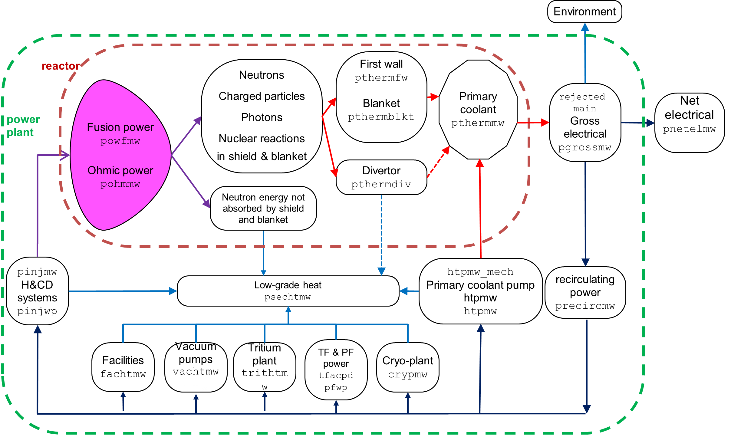
Figure 1 shows a simplified description of the power flow.

Some details of the auxiliary systems are as follows.
tfcpwr calculates the TF coil power conversion system parameters. Only the steady-state power consumption for a superconducting TFC system is described here.
The TF current is carried from the power supplies to the reactor by room-temperature aluminium busbars, organised in N_{circuit} circuits. The total length of the busbars is (somehwat arbitrarily) given by
The resistivity of the busbar is 2.62e-8 ohm.m (0.0262 ohm.mm²/m) (hard-coded).
"TF coil resistive power" (rpower) includes the dissipation of the cryogenic current leads (assumed to be resistive).
The AC power required is determined by the efficiency of the coil power supply: etatf (default = 90%).