Power conversion and heat dissipation systems
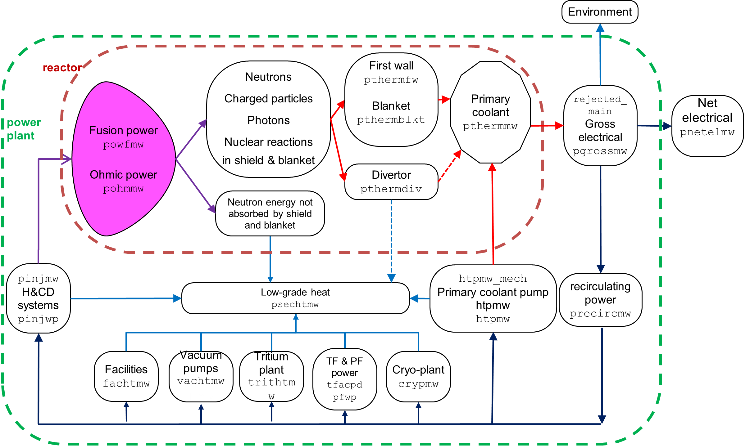
PROCESS takes into account all the systems required to perform the necessary conversion of fusion power to electricity, from the coolant systems in the plant components to the heat exchangers and turbines. Figure 1 shows the power flow.
Divertor
All of the charged particle transport power leaving the plasma (excluding the 1-f_p_alpha_plasma_deposited portion of
the alpha power that escapes directly to the first wall) is assumed to be absorbed in the divertor,
along with a proportion f_ster_div_single of the radiation power and the neutron power.
Switch i_div_primary_heat may be used to specify whether the thermal power deposited in the divertor becomes
high-grade thermal power (i_div_primary_heat = 1) or low-grade waste heat (see Figure 1).
First wall
The photon power is divided into three parts: absorbed by the first wall; incident upon the divertor; and lost through ports. Power due to ions derived from the neutral beams but lost before being thermalised ("first orbit loss"), and from the fast alpha particles lost before being thermalised, also contribute to the total thermal power absorbed by the first wall.
Thermal cycling package
This performs calculations on the first wall of the machine. Evaluations of the mechanical and thermal stresses on this component lead to a measure of the maximum number of cycles to which the first wall can be subjected, and hence to the minimum allowable length of each reactor cycle for a specified first wall lifetime. The cycle time can be constrained to be at least the minimum value by turning on constraint equation no. 42.
Power conversion cycle
The primary coolant (less any thermal power required to produce hydrogen in a hydrogen production plant) is used to heat the secondary coolant to turn the turbines, which power the generator. The remainder is dumped to the environment. All of the low-grade heat is dumped to the environment.
i_p_coolant_pumping : This switch controls the calculation of the mechanical pumping power required
for the primary coolant.
- If
i_p_coolant_pumping= 0, the user sets mechanical pumping directly - If
i_p_coolant_pumping= 1, the user sets mechanical pumping power as a fraction of thermal power removed by coolant. - If
i_p_coolant_pumping= 2, the mechanical pumping power is calculated, as follows:- User inputs for the coolant outlets temperature (which may be used as an iteration variable),
the coolant channel diameter, and the segmentation of the blanket are used. The peak temperature
in the first wall material (underneath the armour) is derived. The user can apply an upper limit
to this temperature, and if this constraint is used then it is strongly recommended to set the
length of the first wall pipe (
len_fw_channel) as an iteration variable. The Gnielinski correlation is used to determine the heat transfer in the channel. The stresses in the first wall are currently taken into account. - The mechanical pumping power required for the first wall and breeder zone is calculated using
the Darcy friction factor, estimated from the Haaland equation, an approximation to the
ColebrookWhite equation. (If you consider that the calculated value for the pumping power is
too low, then you can add an additional electric power requirement using
p_plant_electric_base.) The inlet and outlet temperatures of the first wall and blanket can be different. The isentropic efficiency of the first wall and blanket coolant pumps (enthalpy increase in the fluid for isentropic compression divided by the mechanical power used) is specified by the parameteretaiso. Note that the mechanical pumping power for the shield and divertor are still calculated using the simplified method (a fixed fraction of the heat transported).
- User inputs for the coolant outlets temperature (which may be used as an iteration variable),
the coolant channel diameter, and the segmentation of the blanket are used. The peak temperature
in the first wall material (underneath the armour) is derived. The user can apply an upper limit
to this temperature, and if this constraint is used then it is strongly recommended to set the
length of the first wall pipe (
-
If
i_p_coolant_pumping= 3, the mechanical pumping power is calculated using specified pressure drop. The pressures and temperatures are set by the user.- When used with the DCLL model a different set of pressure drop variables are used, which are outlined below:
Variable Units Default Description dp_fw_blnktPa 1.5D5 Pressure drop in FW and blanket coolant including heat exchanger and pipes dp_fwPa 1.5D5 Pressure drop in FW coolant including heat exchanger and pipes dp_blktPa 3.5D3 Pressure drop in blanket coolant including heat exchanger and pipes dp_liqPa 1.0D7 Pressure drop in liquid metal blanket coolant including heat exchanger and pipes - The defaults for these variables are geared towards a WCLL concept, so different values should be used with Helium cooling.
i_thermal_electric_conversion : This switch controls the calculation of the thermal to electric conversion
efficiency in the secondary cycle.
- If
i_thermal_electric_conversion= 0, the efficiency of the power generation cycle is set to a single value obtained from previous cycle modelling studies. The heat deposited in the Toroidal Field coils divertor coolant is assumed to be at such low temperature that it cannot be used for power generation and is dumped to the environment. - In the remaining options (
i_thermal_electric_conversion= 1, 2 or 3), the heat deposited in the divertor coolant is used for power generation - If
secondary cycle= 1, the efficiency of the power generation cycle is set as above, but the divertor heat is used for electricity generation. - If
i_thermal_electric_conversion= 2, the efficiency of the power generation cycle is input by the user. -
If
i_thermal_electric_conversion= 3, a steam Rankine cycle is assumed. The secondary cycle thermal efficiency (eta_turbine) is calculated from the coolant outlet temperature using simple relations between temperature and efficiency1:\begin{eqnarray*} \eta & = & -2.0219 + 0.3720 \, \mathrm{ln}(T) \,\, \mathrm{(water \, coolant; saturated \, steam \, Rankine \, cycle)} \\ \eta & = & -0.8002 + 0.1802 \, \mathrm{ln}(T) \,\, \mathrm{(helium \, coolant; superheated \, steam \, Rankine \, cycle)} \end{eqnarray*}
-
If
i_thermal_electric_conversion= 4, a supercritical CO_2 Brayton cycle is assumed. The secondary cycle efficiency (eta_turbine) is calculated from the coolant outlet temperature using simple relations between temperature and efficiency from 1:\eta = -2.5043 + 0.4347 \mathrm{log}(T) \,\, \mathrm{(water or helium coolant)}
In the above three equations, T is the temperature (K) of the (secondary) coolant at the inlet to the turbine, assumed to be 20 K below the outlet temperature of the primary coolant.
The electrical power required to operate the power plant itself is the so-called recirculating
electric power (p_plant_electric_recirc_mw). Any surplus is exported to the electricity grid as net electric
power (p_plant_electric_net_mw).
The recirculating power comprises the electrical power required to run all of the associated
electrical systems surrounding the fusion power core, plus the on-site building services, offices,
etc., as shown in Figure 1. Of these, the cryogenic plant power includes the power required to cool
the TF coils from the neutron power absorbed by the coils, the PF coils (as defined by the ratio of
the total PF coil stored energy to the fusion power pulse time t_plant_pulse_plasma_present), and other 'cold' components.